

This is the full text and graphics of the second part of a 2-part article that appeared in the February and March issues of Nuts & Volts Magazine.
Reprinted by permission of Nuts & Volts Magazine ©1999
In part one of this article, we constructed a circuit on a small (2.5
X 3.5 inch) printed circuit board that samples the ambient temperature
and humidity. The THX10 circuit communicates the information to humans
by way of blinking a single LED. It also communicates the information in
the form of an 8-bit binary code to an X10 transmitter that broadcasts
it onto your house's power line. Up to 8 of these transmitters can be placed
throughout your house. Somewhere in your house, a PC, connected to an X10
receiver, collects the data, displays it, and produces listings for all
the remote devices. The monitoring software is written in BASIC, so it
is easy to customize for your own use.
When designing this system, it was difficult to decide which type of transmitter to use. Most circuits that communicate to X10 use a $25 TW523 interface. Since I wanted to have 8 remote units, the thought of $200 just for the transmitters seemed a little out of line. I settled instead on the cheaper ($10-$15) X10 mini controller. You can find the mini controller sold in large hardware stores, at Radio Shacks, or through home automation catalogs. The same unit is sold under the names of X10 Powerhouse, Stanley, Radio Shack, and no doubt many more. The cases may look slightly different, but internally they are identical. They have 6 rocker-type switches; pushing down on the top part of a switch sends an 'on' signal while pushing the bottom sends an 'off' signal. The first 4 switches are for channels 1-4 or 5-8 (a little slide switch selects the 1-4 or 5-8 groups); the 5th switch is for dim/bright, while the 6th switch is for all on/all off. On the left side above the first switch is a LED that glows when a signal is being transmitted. On the right side above the last switch is a rotary switch that sets one of 16 house codes.
![]()
Photo A. The mini controller X10 transmitter
(still in its plastic case).
The THX10 circuit contains two optoisolated integrated circuits. To send an 'on' of 'off' sequence to the mini controller, NPN transistors within the ICs are turned on by a pulse sent from the PIC CPU. These transistor outputs, acting like switches, are wired in parallel with the corresponding switches in the mini-controller. When the mini controller broadcasts the signal onto the power line, it includes house and channel number information in the coded signal, so the receiver can determine who sent it.
For my remote units, I used only the PC board and the connected AC line cord from the mini-controller; I tossed away the plastic case and all the plastic switches. I attached a small 12-volt transformer to the AC in the mini controller to power the THX10 sensor circuit. The two PC boards connect together via a 5-conductor cable - two wires for the 12-volt AC and three wires for the X10 logic signals. Both PC boards were then mounted in the same case (note below that they must be thermally isolated), making a fairly compact (4.5 X 8 X 1.25 inch) unit.
The X10 mini controller is easy to interface and most home experimenters should be capable of handling the job. However, precautions should be taken when the unit is plugged into the AC line. The mini controller circuit uses no isolation transformers, so the circuit is at 117-volt potential when it is plugged in. NEVER work on or touch anything on the board when line voltage is present! The THX10 circuit is adequately isolated from the AC: the three logic lines are passed to optoisolator ICs, while the 12-volt AC is isolated by way of the transformer T1.
When working on the mini-controller board, the first thing you should do is decide which house code and channel number is required. All of the remote units must be set to the same house code, while every one of them must be set to a different channel. Photo 1 shows what I call the bottom of the board, the side with the soldering (in the mini controller case, it is really the top side). The house code is set by what's left of the rotary switch in the upper right corner. A small solder blob across the three switch contacts as shown will decode to house code 'F'. If you desire a different house code programmed, try to figure out which contacts would be connected together by the switch and solder some small jumper wires onto the PC board contacts. A small blob of solder is also needed to select either the '1-4' or '5-8' channel groupings. For the first unit, solder across the two terminals at the left, as shown near the bottom of the board. When constructing a unit for channels 5-8, put a blob across the center and the right terminal, instead.
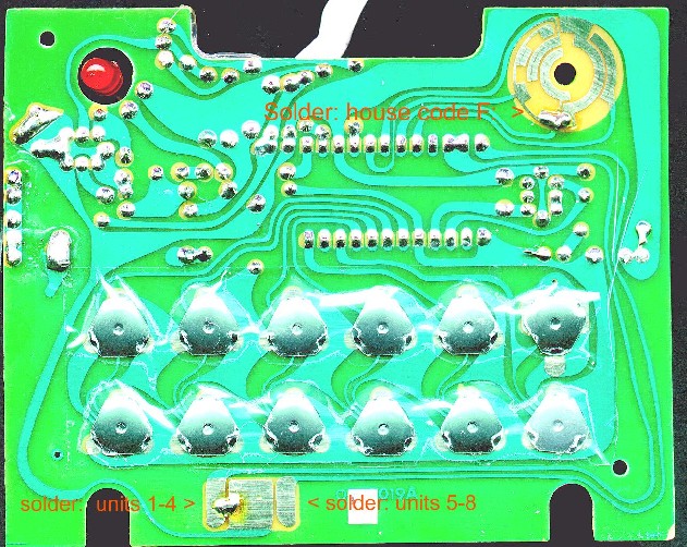
Photo 1. Bottom (foil) side of the mini controller
PC board.
The other side of the PC board is shown in Photo 2, what I call the top side. Here, I cemented the transformer T1 into the large open area at the bottom using a glue gun. Note that the terminals are upward to make it easy to solder wires to them. The two black wires on the top side of the transformer (pins 1 and 5) are fed through two pre-existing, unused holes to solder pads on the other side to pick up the 117-volt AC. The one at the left (AC-1) connects to the large circuit area that goes all the way up and around the rotary house code switch. The other one (AC-2) is placed in one of 5 holes in a vertical line that join a capacitor, a resistor, and a little wire. Actually the little wire is a fuse. Note that this fuse is between the power cord and our AC-2 wire. The fuse is thus protecting the mini controller circuitry and our THX10 circuit (for which the power drain is negligible).
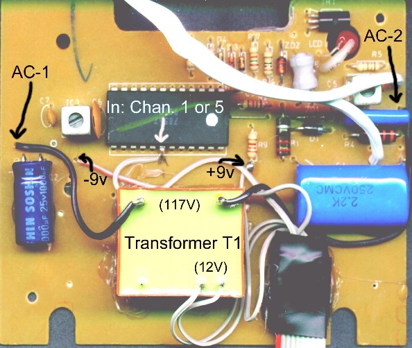
Photo 2. Top (component) side of the mini controller
PC board.
A 5-conductor wire is used to connect to the 12-volt output of the transformer T1 and 3 logic lines. The #1 and #2 wires can be seen connecting to the terminals at the bottom of the transformer (pins 6 and 7). The other 3 wires need some explanation. The #3 wire connects to what I refer to as +9v which is found at the bottom end of a 3300-ohm resistor, as shown. The #5 wire (what I call -9v) goes into a pre-existing, unused hole below the metal can near the left about halfway up (see the Photo). The placement of the remaining wire (#4) depends on which channel this is to be used for. For channel 1 or 5, it connects to pin 18 of the large IC. For channels 2 or 6: pin 19; for channels 3 or 7: pin 20; and for channels 4 or 8: pin 21. I made a small solder bead directly onto pin 18 of the IC and then tacked on the pre-tinned wire end with a low-power pencil-type soldering iron.
The 5-conductor cable is then connected to a female connector to mate with the header on the THX10 board. Before connecting the two boards together, first test the wired mini controller board by itself. For the first test, just plug in the AC line cord and make sure that nothing is smoking. Then using a small meter set to AC, validate that wires #1 and #2 of the 5-conductor cable is supplying 12-volt AC. Assuming all is well so far, unplug the unit, and connect a meter set to a 20-volt or higher DC scale to wires #3 and #5. Then without touching anything, plug in the AC cord. You should see about 16 to 18 volt across these two wires on your meter. Then unplug the AC cord.
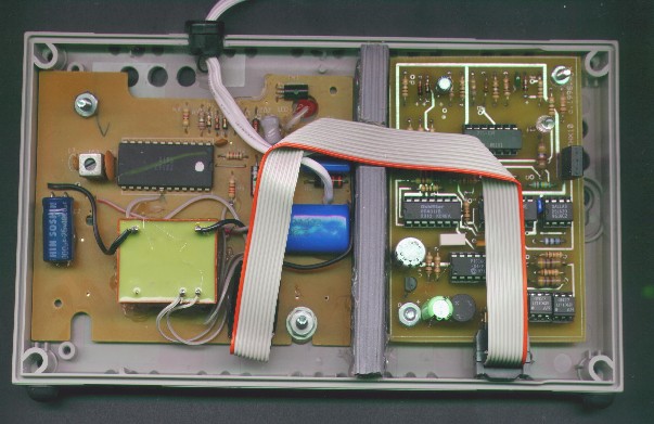
Photo 3. Mini controller and THX10 PC boards
in half of the enclosure.
Assuming everything is wired up correctly, make sure the AC cord is unplugged, and connect the 2 PC boards, making sure wire #1 (the 12-volt AC) goes onto pin 1 of J1. Then plug in the AC cord. The THX10 board will then be powered via the 12-volt AC supply. After a few seconds the 3-blink self test should appear on the THX10 LED. After a few more seconds, the LED on the mini controller should start to blink. You should see 8 blinks. These are the 8 bits that make up the temperature measurement. When the mini-controller LED is finished, the LED on the THX10 board should start to blink, this time counting out the temperature in degrees F. If all goes well, then, the circuits are working fine together. Unplug the AC line cord and prepare the enclosure.
I used a small plastic case for the boards. In retrospect, I probably should have used one slightly larger, but the 4.5 X 8 X 1.25 size is now working fine. The biggest problem of putting both boards into one case is that the mini controller PC board generates heat, enough heat to affect the sensors of the THX10 board. Therefore, you must thermally insulate two compartments in the same case, and vent each side separately. Photo 3 shows the two boards in one half of the enclosure. Note the rubberized weather stripping between them; there is also weather stripping cemented in the same line on the other half of the enclosure. This keeps the heat on the mini-controller side. A large number of holes must be drilled on both ends. I oriented the case so the boards extend vertically, meaning the thin 1.25 inch side of the case is the base. A number of holes were drilled along both the bottom and the top sides to produce a 'chimney' effect that draws the heated air upward past the boards in each compartment. This venting plus the thermal barrier (weather-stripping) is sufficient to isolate the two compartments thermally. Also drill a few holes in very close proximity to the two sensors. Note that even though the two compartments of the case are thermally separate, the THX10 PC board is oriented so that the sensors are as far away from the mini controller board as possible.
For the front side of the case, drill a hole for LED1 while you are drilling all the vent holes. The PC boards are mounted to the back side using small screws and nuts. Use a grommet for a hole along the junction of the two halves to pass the line cord out of the case. Screw the two case halves together, and you're done. There is no on/off switch. When you don't want it on, just unplug it. The mini controller is designed to run constantly, as is the THX10. If power should go out, when it comes back on, the THX10 will merely go through the self-test, then start to transmit.
To receive the X10 codes from the remotes scattered throughout the house, I use an interface known at the CM11A X10 ActiveHome Two-Way Universal Computer Interface. The interface comes with software on CD (CK11A) as part of X10's 'Home Automation System'. The CM11A is a small cube (about the size of a power cube) that plugs into a 117-volt wall socket. It has a convenience outlet on the front. X10's literature says you should plug your computer into this outlet; this is to ensure that both the CM11A and your PC are both connected to the same ground. The CM11A comes with a small cable that has a 9-pin RS/232 plug that should be connected to the serial port on a PC. If you want to use it with a 25-pin serial socket, you'll have to get a 9-pin to 25-pin converter, available at most stores selling PC equipment.
Although not as easy to find as the mini controllers, you shouldn't have any trouble obtaining a CM11A. Radio Shack has one bundled with a few X10 light switches as a Home Automation System. You can order the unit from several home automation catalogs (see parts list); it costs about $45.
Photo B. The CM11A X10 receiver.
The CM11A device is intended to communicate with and monitor other X10 devices on the power line. It has internal memory in which macros can be stored. A macro works like this: it is set to activate when it receives a certain channel code on a certain house code; it will then output a sequence of codes to other X10 units so that one light switch can be used to set off a whole sequence of events. The CM11A has battery backup so that it will remember the macros when the computer is off or even on power outages. The software on CD allows you to program the macros, monitor X10 devices, generate output signals, etc. For our purposes, there Is no need to install the software (unless you're dying to see how it works), or to install batteries, since we won't be using macros.
On the CD that comes with the CM11A, you can find a program 'COMTEST.EXE' that you can run from DOS or Windows that can be used to debug X10 systems. It monitors all the X10 activity on the house's wiring and prints it to the screen. With it, you can verify that your THX10 is actually sending out the 'on' and 'off' commands and that they are being sent on the proper house code and channel numbers.
Also on the CD, you can find an information file called PROTOCOL.DOC (in Word format), or PROTOCOL.TXT (in plain text). This document explains how you can write your own programs to use the CM11A. It is quite complex, but a few things are worth noting. First, the interface uses 4800 baud, pretty slow by today's standards. Second, it has a maximum buffer size of 10 bytes. Since every X10 signal consists of multiple bytes, and since the baud rate is slow, any software using the CM11A must be written to make data transmission from the CM11A to the PC very high priority. Failure to do so could result in some loss of data from subsequent X10 control signals.
The COMTEST program can be used to make sure everything is working, but more customized software is needed to take advantage of the THX10 remote sensors. A BASIC program was written to at least get you started.
The diskette supplied with the THX10 chip contains two BASIC programs
that can be used to monitor the temperature and humidity from multiple
transmitters. The programs are:
* THMONITG.BAS - this program will work with GWBASIC, supplied with
DOS versions 2-5.
* THMONITQ.BAS - this program will work with QBASIC, supplied with
newer versions of DOS and Windows 3.1
Either of these programs will work with Windows 95/98, by running either
of the GWBASIC or QBASIC interpreters. If you are running Windows 95/98
and do not have either of these BASIC interpreters, you can copy the appropriate
GWBASIC.EXE or QBASIC.EXE files from an older computer to your new computer.
The BASIC program can be run from DOS or Windows 3.1 for testing and debugging, but this is not recommended for full-time monitoring. These older operating systems do not support multiprocessing, so while the monitor program is running, your PC cannot can not do anything else. One thing that you may want to do concurrently is to review older log files. If you are running the monitor program in a DOS window in Windows 3.1, you can click on another window to review or print the log files, but in doing so, the monitor program will be temporarily off-line. Doing the same thing in a Windows 95/98 window will allow the monitor program to continue to run at the same time that you are inspecting log files, printing, etc.
Using QBASIC
Use the 'Start', 'Run...' menus. Either type in the pathname and filename
(such as C:\DOS\QBASIC.EXE) and 'Open', or find the file by the 'Browse'
menu and then open it. You will see an opening screen; press the escape
key, then use the menus ('File', 'Open') to load the basic program 'THMONITQ.BAS'.
Then use the menus ('Run' then 'Start') to run the program. After a few
seconds, you will see the time of day at the bottom of the screen, indicating
that it is running.
Using GWBASIC
Use the 'Start', 'Run...' menus. Either type in the pathname and filename
(such as C:\DOS\GWBASIC.EXE) and 'Open', or find the file by the 'Browse'
menu and then open it. You will see an 'OK' printed out. Type the sequence:
LOAD "xxxxTHMONITG.BAS", where xxxx is filled in with the path to the program,
such as C:\DOS\ or A:\, or wherever you have placed the THMONITG.BAS file.
To confirm that it loaded type LIST, and you should see the program listing
scroll past. To run it, type RUN.
To toggle back and forth from a full-size screen to a window on the desktop, press 'Alt-Enter' (both keys at once). If you want to quit the program, press 'Ctrl-Break' (two keys at once). To exit GWBASIC, type SYSTEM. To exit QBASIC, use the menus.
Customizations
The programs are set up for serial port 1 (COM1), and for monitoring
X10 house code 'F'. If either of these need changed, you should update
the statements in lines 20 and 30 of the program for your serial port or
house code.
The monitor program talks to a CM11A interface through the serial port of your PC. The CM11A monitors all X10 communications on your house's power line. The program decodes the information coming from the CM11A and sends back appropriate handshaking information. The monitor program determines if the X10 information corresponds to the specific house code that you are monitoring (default is house code 'F'). If so, it saves the information in a buffer for each allowable channel (1 through 8), and when enough information is attained, it takes appropriate action.
The temperature/humidity transmitter sends the data as a series of 8 'on' or 'off' X10 sequences to build up a byte (8 bits). When the 8th bit is received, the program figures out if it is a temperature (binary value of 0-127) or humidity (128-255). For the humidity data, the 8th bit is stripped off. The data is printed on the screen immediately after it is received. The value is compared to a running average for that channel; if it is more than 15 units from the average, it is assumed to be garbled and it is discarded. Good data is retained and later printed out as part of the hourly average in the log file created for that day.
The temperature/humidity transmitters send one set of data every 5-6 minutes, alternating between temperature and humidity. Typically each channel will then send about 5-6 temperatures and 5-6 humidities every hour. If all 8 channels are active, this means over 80 sets of data every hour. The more active channels, the higher the chance for data collisions. When more than one transmitter is sending data at exactly the same instant, there is a good chance that one of them will be ignored by the CM11A receiver. When this happens, the full 8 bits for the sample will never be received. To handle this, the program uses timeouts.
A timeout will occur if more than 1 but less than 8 bits are received within a 3-minute period for any specific channel. A timeout means the data is incomplete and it is discarded; it resets the bit counters for that channel so the next series (5-6 minutes later) can be received. Timeouts will occur due to data collisions using more than one channel. Since environmental monitoring is not a mission-critical application, and actual temperature and humidity changes usually take 20-30 minutes, a loss of a few samples is not a problem.
A new log file is created on disk for each day that the monitor program is running. The date is encoded in the file name (for example 'TH981215.LOG' is the file created for December 15, 1998). The file is written out at midnight and a file for the new day is then opened. The log file lists one line of information for every active channel every hour (0-23). An active channel is any channel on the house code for which there was any activity: temperature, humidity, timeouts, or errors. The average for the hour is printed out with the number of samples in parenthesis for both temperature and humidity. The number of timeouts and errors is also printed out. The last thing on each line is the heat index calculation for the average temperature and humidity.
While the program is running, the time of day is continually updated at the bottom of the screen. When any transmitter for the monitored house code is received, the channel number will appear at the bottom left side of the screen. The channel number will remain on the screen until either the full 8 bits are received, or there is a timeout. When the full 8 bits are received, one line of information is scrolled onto the screen showing the channel number, the type and the data (temperature or humidity), and the time received. The program will also monitor other house codes and display the house code received at the bottom right of the screen for a few seconds.
The monitor program currently does the bare minimum. It keeps track of data from the CM11A, it decodes it, it fills matrices for temperatures and humidities, and it prints averages to log files on disk. It probably doesn't do everything YOU want it to do. For example, you may want to send data to a printer, take action if the temperature or humidity falls outside of a predetermined range, etc. You might want to send commands to the CM11A to transmit data, for example on a different house code that is monitored by another CM11A connected to a PC and a heating/air-conditioning system. Stub subroutines are jumped to when valid data is received; you can add your routines there. Feel free to change the program, port it to Visual Basic, port it to C, C++, or Java, or port it to Linux Send any major modifications to me via email: mkeryan@pobox.com.
[Note: More robust software
written in C for Linux systems is now available.]
[E-mail the author for more
information.]
The best locations for the THX10 remote units are:
You may find that after a power outage, you get a lot of timeouts and/or bad data for a while. This is because all the THX10 units came up at the same moment when the power came back on and are in sync; they are all trying to send data at exactly the same time. This causes data collisions, and a loss of data. After a while, they will get out of sync all by themselves because the resonators clocking the PIC CPUs are not very precise. You can speed up this process to randomize the sequencing by uplugging and then plugging back in several of the units, one at a time, at 1-minute intervals.
Occasionally, even without a power failure, this synchronization will occur between two or more units, and you will lose some data until they fall out of sync. The system is based on redundancy; your monitoring software should make decisions based on a consensus of results, not just on one particular sensor. That way, if data from any one sensor is lost, the whole system continues to operate.
0 REM THMONITG.BAS --
WORKS WITH GWBASIC
1 REM BASIC
PROGRAM TO MONITOR TEMPERATURE AND HUMIDITY
2 REM COMMUNICATES
WITH X10 CM-11 INTERFACE AS RECEIVER FOR THX10
3 REM COPYRIGHT
1998 M.KERYAN
4 REM
SET YOUR SERIAL PORT IN RS% -- LINE 20
5 REM
SET YOUR HOUSE CODE IN H$, AND ORDER # IN TH -- LINE 30
6 REM
USE THIS TABLE TO FIND ORDER FOR THE HOUSE CODES:
7 REM
CODE: A B C D E F G H
I J K L M N O P
8 REM
ORDER: 6 14 2 10 1 9 5 13 7 15
3 11 0 8 4 12
9 REM USER
ROUTINES CAN BE ADDED IN SUBROUTINES AT LINES 4000 AND 5000
10 CLEAR: KEY OFF
20 RS% = 1
30 H$ = "F": TH = 9
100 REM VARIABLES:
110 REM A$
TEMPORARY STRING
120 REM AC(NA)
ACTIVE CHANNEL # FROM INTERFACE
122 REM AH(7)
RUNNING AVG. HUMID. FOR EA. CHAN.
124 REM AT(7)
RUNNING AVG. TEMP. FOR EA. CHAN.
130 REM B
BIT, 0 OR 1
140 REM BC
BITCODE, TEMP FOR NB%
150 REM BD
BITDATA, TEMP
160 REM BY%(7) BYTE
FOR EA. CHAN., TEMP HOLDING
170 REM C
CHAR FROM BUFFER
171 REM CA%(255)
CHAR. BUFFER
172 REM CB%
BEGINNING OF CHAR. BUFFER
173 REM CE%
END OF CHAR. BUFFER
175 REM CI
CHARACTER INPUT
176 REM CM%
MAXIMUM BUFFER SIZE
180 REM CN
CHAN. NO. RECEIVED
190 REM D%
DEV. CODE OR COMMAND CODE
200 REM DC
DEV. # (TRANSLATED)
210 REM H$
HOUSE CODE STRING TO LOOK FOR
220 REM H
HOUSE CODE RECEIVED
225 REM HI
HEAT INDEX
230 REM I
TEMP INDEX COUNTER
240 REM IM
IS MASK, FLAG = 1 IF MASK, -1 IF NOT
250 REM MA
MASK BYTE FROM INTERFACE
260 REM NA
COUNTER OF ACTIVE CHANNEL
270 REM N%(15)
X10 CODE ORDER
280 REM NB%(7)
NUM.BIT FOR EA. CHAN.
285 REM NE%(7)
NUMBER OF ERRORS FOR HR
290 REM NO%(7)
NUMBER OF TIMEOUTS FOR HR
300 REM NH%(7)
NUMBER OF HUMID. SAMPLES FOR HR
310 REM NT%(7)
NUMBER OF TEMPER. SAMPLES FOR HR
320 REM NC
NUMB. OF CHAR TO FOLLOW FROM INTERFACE
330 REM OH$
OLD HOUR
340 REM OM$
OLD MINUTE
350 REM OS$
OLD SECOND
360 REM RES$
RESPONSE STR
370 REM RS$
SERIAL PORT ("COM1" OR "COM2")
371 REM RS%
SERIAL PORT (1 OR 2)
380 REM SM%(7)
START MINUTE (0-1439) FOR CHAN
385 REM SN%(7)
STABLE NOW COUNTER FOR CHAN (STABLE IF > 10)
390 REM SH(7)
SUM HUMIDITY FOR HR
400 REM ST(7)
SUM TEMPERATURE FOR HR
410 REM TH
THIS HOUSE # TO LOOK FOR
420 REM TI$
TIME STRING
430 REM TM
THIS MASK; MASK BIT FOR A BYTE, 0 OR 1
432 REM UH%(7)
UNSTABLE COUNTER FOR EA. CHAN
434 REM UT%(7)
UNSTABLE COUNTER FOR EA. CHAN
440 REM X%
TEMPORARY X
450 REM Y%
TEMPORARY Y
460 REM Z%
TEMPORARY Z
470 REM Z$
ZERO CHAR
900 REM
1000 REM START OF PROGRAM
1010 CLS : FOR I = 1 TO 25: PRINT : NEXT
I
1020 GOSUB 1100
1030 ON COM(RS%) GOSUB 3000
1040 COM(RS%) ON
1060 IF (CE% = CB%) THEN 1080
1070 GOSUB 3100: GOSUB 2000
1080 GOSUB 1200
1090 GOTO 1060
1100 Z$ = CHR$(&H0): RES$ = CHR$(&H9B)
+ STRING$(6, Z$)
1105 RS$ = "COM" + RIGHT$(STR$(RS%), 1)
1110 RS$ = RS$ + ":4800,N,8,1,RS,CS0,DS0,CD0":
OPEN RS$ FOR RANDOM AS #2
1130 DATA 12,4,2,10,14,6,0,8,13,5,3,11,15,7,1,9
1140 DIM N%(15): FOR I = 0 TO 15: READ
N%(I): NEXT I
1150 DIM NB%(7), BY%(7), SM%(7): FOR I
= 0 TO 7: SM%(I) = -1: NEXT I
1160 DIM SH(7), ST(7), NO%(7), NE%(7),
NH%(7), NT%(7), CA%(255)
1165 DIM AH(7), AT(7), SN%(7), UH%(7),
UT%(7)
1170 A$ = TIME$
1175 IF (A$ = TIME$) GOTO 1175
1180 A$ = "TH" + RIGHT$(DATE$, 2) + LEFT$(DATE$,
2) + MID$(DATE$, 4, 2) + ".LOG"
1185 OPEN A$ FOR OUTPUT AS #3: PRINT #3,
"LOG for "; DATE$; " started "; TIME$;
1190 PRINT #3, " X-10 House Code "; H$
1199 RETURN
1200 TI$ = TIME$
1210 IF (LEFT$(TI$, 2) <> OH$) THEN
GOSUB 1300: OH$ = LEFT$(TI$, 2)
1220 IF (MID$(TI$, 4, 2) <> OM$) THEN
GOSUB 1400: OM$ = MID$(TI$, 4, 2)
1230 IF (RIGHT$(TI$, 2) <> OS$) THEN
GOSUB 1500: OS$ = RIGHT$(TI$, 2)
1240 RETURN
1300 IF (OH$ = "") THEN RETURN
1310 PRINT #3, "": PRINT #3, "Averages
for Hour "; OH$
1320 FOR I = 0 TO 7: IF ((NO%(I) + NE%(I)
+ NH%(I) + NT%(I)) = 0) GOTO 1370
1330 X% = 0: IF (NH%(I) > 0) THEN X% =
CINT(SH(I) / NH%(I))
1340 Y% = 0: IF (NT%(I) > 0) THEN Y% =
CINT(ST(I) / NT%(I))
1350 PRINT #3, USING "Ch. # "; (I + 1);
1352 PRINT #3, USING "### deg F "; Y%;
: PRINT #3, USING "(#) "; NT%(I);
1354 PRINT #3, USING "### % RH "; X%;
: PRINT #3, USING "(#) "; NH%(I);
1360 PRINT #3, USING "## Time-outs"; NO%(I);
1365 PRINT #3, USING " ## Bad data"; NE%(I);
1367 GOSUB 3500: PRINT #3, USING "
Heat Index: ###"; HI
1370 NEXT I: FOR I = 0 TO 7: NO%(I) =
0: NE%(I) = 0: NH%(I) = 0: NT%(I) = 0
1380 SH(I) = 0: ST(I) = 0: NEXT I
1385 IF (OH$ = "23") THEN PRINT #3, "Maximum
character buffer:"; CM%
1390 IF (((OH$ = "24") OR (OH$ = "23"))
AND (LEFT$(TI$, 2) = "00")) GOTO 10
1399 RETURN
1400 FOR I = 0 TO 7: IF (SM%(I) < 0)
GOTO 1450
1410 X% = VAL(OM$) + 60 * VAL(OH$)
1420 IF ((X% - SM%(I)) < 3) GOTO 1450
1430 CN = I: PRINT "Ch."; (CN + 1); "
Time-out "; TI$: GOSUB 2900
1440 NO%(CN) = NO%(CN) + 1
1450 NEXT I: GOSUB 1650
1460 IF (RIGHT$(OM$, 1) = "2") THEN I
= FRE(A$)
1490 RETURN
1500 Y% = CSRLIN: X% = POS(0): LOCATE
25, 20: PRINT TI$; : LOCATE Y%, X%
1510 IF (RIGHT$(OS$, 1) = "2") THEN A$
= " ": Z% = 50: CN
= 0: GOSUB 1680
1590 RETURN
1600 A$ = CHR$(CN + 49): Z% = 0: GOTO
1680
1610 A$ = " ": Z% = 0: GOTO 1680
1620 I = N%(CN)
1630 CN = I: A$ = CHR$(CN + 65): Z% =
30: GOTO 1680
1650 A$ = "
": CN = 0: Z% = 30: GOTO 1680
1680 Y% = CSRLIN: X% = POS(0): LOCATE
25, FIX(CN + Z% + 1): PRINT A$;
1690 LOCATE Y%, X%: RETURN
2000 REM
2010 IF (NC > 0) THEN NC = NC - 1: GOTO
2100
2020 IF (C = 90) THEN PRINT #2, CHR$(&HC3);
: RETURN
2030 IF (C = 165) THEN PRINT #2, RES$;
: RETURN
2040 IF (C = 0) THEN PRINT #2, Z$; : RETURN
2050 IF (C = 85) THEN RETURN
2060 IF (C > 9) THEN PRINT "ERR " + HEX$(C):
RETURN
2070 NC = C: IM = -1: RETURN
2100 IF IM < 0 THEN MA = C * 2: IM
= 1: RETURN
2110 MA = MA / 2: TM = INT(MA) AND 1
2120 H = INT(C) AND 240: H = H / 16: D%
= INT(C) AND 15
2130 CN = H: GOSUB 1620: IF (H <> TH)
THEN RETURN
2140 IF (TM = 1) GOTO 2200
2150 DC = N%(D%)
2170 IF (DC = 999) THEN RETURN
2180 AC(NA) = DC: NA = NA + 1: RETURN
2200 IF ((D% < 2) OR (D% > 3)) THEN
NA = 0: RETURN
2210 B = 1: IF (D% = 3) THEN B = 0
2220 FOR I = 0 TO (NA - 1): CN = AC(I):
BC = NB%(CN)
2230 IF (BC = 0) THEN BC = 1: BD = 1 AND
INT(B): SM%(CN) = VAL(OM$) + 60 * VAL(OH$): GOSUB 1600: GOTO 2250
2240 BC = BC * 2: BD = INT(BC) * INT(B)
2250 BY%(CN) = BY%(CN) + INT(BD): NB%(CN)
= INT(BC)
2260 IF (BC > 127) THEN GOSUB 2500
2270 NEXT I: NA = 0: RETURN
2500 Z% = BY%(CN) AND 127
2510 PRINT "Ch."; (CN + 1); RIGHT$("
" + STR$(Z%), 4);
2520 SN%(CN) = SN%(CN) + 1
2530 IF (BY%(CN) > 127) GOTO 2700
2600 PRINT " Deg F "; TI$;
2610 IF (SN%(CN) < 10) GOTO 2650
2620 IF (ABS(Z% - AT(CN)) < 16) GOTO
2640
2630 PRINT " ERROR ASSUMED";
: NE%(CN) = NE%(CN) + 1: GOTO 2800
2640 AT(CN) = (4 * AT(CN) + Z%) / 5: GOTO
2670
2650 AT(CN) = UT%(CN) * AT(CN) + Z%
2660 UT%(CN) = UT%(CN) + 1: AT(CN) = AT(CN)
/ UT%(CN)
2670 ST(CN) = ST(CN) + Z%: NT%(CN) = NT%(CN)
+ 1
2672 IF (UH%(CN) = 0) GOTO 2680
2675 Y% = Z%: X% = AH(CN): GOSUB 3500:
PRINT USING " Heat Index: ###"; HI;
2680 GOSUB 4000: GOTO 2800
2700 PRINT " % RH ";
TI$;
2710 IF (SN%(CN) < 10) GOTO 2750
2720 IF (ABS(Z% - AH(CN)) < 16) GOTO
2740
2730 PRINT " ERROR ASSUMED";
: NE%(CN) = NE%(CN) + 1: GOTO 2800
2740 AH(CN) = (4 * AH(CN) + Z%) / 5: GOTO
2770
2750 AH(CN) = UH%(CN) * AH(CN) + Z%
2760 UH%(CN) = UH%(CN) + 1: AH(CN) = AH(CN)
/ UH%(CN)
2770 SH(CN) = SH(CN) + Z%: NH%(CN) = NH%(CN)
+ 1
2772 IF (UT%(CN) = 0) GOTO 2780
2775 X% = Z%: Y% = AT(CN): GOSUB 3500:
PRINT USING " Heat Index: ###"; HI;
2780 GOSUB 5000
2800 PRINT " "
2899 REM USE THIS TO DEBUG
PRINT #3, BY%(CN); "="; Z%; " ";
2900 NB%(CN) = 0: BY%(CN) = 0: SM%(CN)
= -1: GOSUB 1610: RETURN
3000 IF (EOF(2)) THEN RETURN
3010 CI = ASC(INPUT$(1, #2))
3020 CE% = CE% + 1: IF (CE% > 255) THEN
CE% = CE% - 256
3030 CA%(CE%) = CI: GOTO 3000
3100 CB% = CB% + 1: IF (CB% > 255) THEN
CB% = CB% - 256
3110 C = CA%(CB%)
3120 X% = CE% - CB% + 1: IF (X% < 0)
THEN X% = X% + 256
3130 IF (X% > CM%) THEN CM% = X%
3140 CN = 0: Z% = 50: A$ = "Buf: " + STR$(X%)
+ " ": GOSUB 1680
3150 RETURN
3500 HI = -42.379 + 2.04901523# * Y% +
10.1433127# * X% - .22475541# * Y% * X%
3510 HI = HI - 6.83783 * 10 ^ -3 * Y%
* Y% - 5.481717 * 10 ^ -2 * X% * X%
3520 HI = HI + 1.22874 * 10 ^ -3 * Y%
* Y% * X%
3530 HI = HI + 8.5282 * 10 ^ -4 * Y% *
X% * X%
3540 HI = HI - 1.99 * 10 ^ -6 * Y% * Y%
* X% * X%
3550 RETURN
4000 REM ADD YOUR ROUTINE HERE FOR ACTION
ON TEMPERATURE
4010 REM TEMPERATURE IS IN VARIABLE Z%
4990 RETURN
5000 REM ADD YOUR ROUTINE HERE FOR ACTION
ON HUMIDITY
5010 REM HUMIDITY IS IN VARIABLE Z%
5990 RETURN