

This is the full text and graphics of the first part of a 2-part article that appeared in the February and March issues of Nuts & Volts Magazine.
Reprinted by permission of Nuts & Volts Magazine ©1999
The THX10 remote monitoring system described in this article is inexpensive, accurate, and flexible. You can buy sensors that sample and report accurate temperature and humidity data, but they will probably set you back over $100 apiece. And even if you had the money to buy enough of them to monitor most of the rooms in your house and to purchase an expensive master monitoring station, you would still have to run a bunch of wires around your house to connect everything.
Or you can build one of more of the sensor units described in this article. You can pick up the X10 interface equipment at your local Radio Shack. With THX10 you won't have to calibrate anything or string up any wires between rooms. And you can customize the monitor software yourself, because it is written in BASIC.
In part one of the two-part article, we'll talk a little about humidity, describe how the circuit works, and how to build the sensor circuitry. In part two, we'll show how to connect the sensor circuitry to an X10 interface, and how the X10 receiver and software works.
Ever since we moved from up North to South Carolina several years ago, my family and I have not been able to adjust to the temperature. Not outside; the temperature outside is nearly always warm to hot and your body seems to become accustomed to that. The problem is inside, where the windows and doors are kept closed and the environment is supposedly controlled. Temperature fluctuations are kept to a minimum thanks to the heating and air-conditioning systems and programmable thermostats. However, it almost never feels ideal. Most of the time, it feels either too warm or too cool, even though the thermostats both upstairs and downstairs swear that the temperature hasn't changed. What they don't tell us anything about is the humidity.
Our HVAC systems work very hard to maintain a constant temperature, because our bodies are greatly affected by the temperature. However, human bodies, as well as many other living and non-living things, are also greatly affected by the humidity. Our natural cooling system is dependent on our sweat being able to evaporate. If the humidity is very high, the moisture we secrete out of our sweat glands tends to remain on our skin; there is no significant gradient between the moisture on our moist skin to the moist atmosphere, so we experience no cooling effect. On the other hand, when the humidity is very low, moisture on our skin evaporates very quickly into the relatively moisture-free atmosphere. When this evaporation takes place, a certain amount of heat is given up from our skin to the environment, and our skin feels cool. When our skin feels cool, we feel cool.
Air at any specific temperature can only hold a finite amount of water vapor. When the air is forced to hold as much moisture as possible, it is said to be saturated. At higher temperatures, the air can hold larger amounts of water vapor, in fact much larger amounts - it is an exponential relationship. Relative Humidity is defined as the amount of water vapor that is currently present in the air, divided by the maximum that the air can hold at that same temperature. Therefore, there is a lot more moisture in the air at 90 deg F, 90 % RH, than at 80 deg F, 90 % RH.
We can generate what is known as the heat index, using both temperature and humidity. The heat index is probably a better indicator of how we feel than either temperature or humidity alone. The heat index accounts for the ability of moisture to evaporate (low humidity) or to not evaporate (high humidity). Table 1. shows the heat index for temperatures and humidities in 10 deg/% increments. Note the example above: 80 deg F, 90 % RH feels like 88 deg, but 90 deg F, 90 % RH feels like a whopping 122 deg! Prolonged exposure and physical activity at a heat index of greater than 90 can cause heat exhaustion, while an index greater than 100 can lead to heat stroke. While the temperatures in our homes are not likely in this high a range, you can see from the chart that humidity does have an affect even at room temperatures, in the 60-90 deg F range. High humidities in the 80-90 deg F range make it feel 5 or more degrees warmer, while low humidities in the 60-70 deg F range make it feel 5 or more degrees cooler than a thermostat would say.
| Air Temperature, deg. F. | |||||||||||
|---|---|---|---|---|---|---|---|---|---|---|---|
| 70 | 75 | 80 | 85 | 90 | 95 | 100 | 105 | 110 | 115 | 120 | |
| Relative Humidity |
|
||||||||||
| 0% | 64 | 69 | 73 | 78 | 83 | 87 | 91 | 95 | 99 | 103 | 107 |
| 10% | 65 | 70 | 75 | 80 | 85 | 90 | 95 | 100 | 105 | 111 | 116 |
| 20% | 66 | 72 | 77 | 82 | 87 | 93 | 99 | 105 | 112 | 120 | 130 |
| 30% | 67 | 73 | 78 | 84 | 90 | 96 | 104 | 113 | 123 | 135 | 148 |
| 40% | 68 | 74 | 79 | 86 | 93 | 101 | 110 | 123 | 137 | 151 | |
| 50% | 69 | 75 | 81 | 88 | 96 | 107 | 120 | 135 | 150 | ||
| 60% | 70 | 76 | 82 | 90 | 100 | 114 | 132 | 149 | |||
| 70% | 70 | 77 | 85 | 93 | 106 | 124 | 144 | ||||
| 80% | 71 | 78 | 86 | 97 | 113 | 136 | 157 | ||||
| 90% | 71 | 79 | 88 | 102 | 122 | 150 | 170 | ||||
| 100% | 72 | 80 | 91 | 108 | 133 | 166 | |||||
So why don't our thermostats measure heat index, rather than just temperature? One big reason is that monitoring and detecting water vapor is much more difficult than measuring other parameters, such as temperature, pressure, etc. Humidity sensors tend to have limited lifetimes, most are highly non-linear and highly temperature-dependent, and they typically have very high part-to-part tolerances, meaning they must be calibrated. A typical calibration involves placing certain salt solutions in closed containers to give known humidity levels. This is not practical for most manufacturers, and probably nearly impossible for most home tinkerers.
The circuitry in this article is designed around a humidity sensor distributed by Figaro USA, Inc. The NH-03 sensor contains two relative humidity sensitive elements, made from a stable high polymer impregnated in porous ceramic. The sensor also contains two printed NTC thermistors on an alumina ceramic substrate. The network of humidity and temperature sensors provide temperature compensation as well as a linear output. The sensor is provided in a small (10mm x 12 mm x 4 mm) plastic package with 3 leads, spaced 0.1 inch apart. Figaro states the overall long-term accuracy of the sensor to be +/- 10% for 0-40 deg C (50-104 deg F) and 30-80 %RH, but when used in the self-calibrating circuit (see below), deviations greater than about 3% RH haven't been detected.
Humidity measurement is complicated by the fact that any DC voltage applied to the sensor will degrade the humidity-sensitive elements. In a typical humidity measuring operation, an AC voltage of precisely 1-volt, 1-kHz is supplied across pins pins 1 and 3 of the sensor. The output is an AC voltage across pins 1 and 2. This AC output voltage is nearly a linear relationship with the % Relative Humidity. Due to the sensor network, the output is basically independent of fluctuations in temperature and frequency. However, the output is very sensitive to the actual level of input AC voltage as well as our ability to accurately measure small AC voltages.
A self-calibration technique is used to overcome the problems with the small AC voltages. Circuitry is provided to change the output AC voltage to a DC voltage and then translate the DC voltage to a pulse width. The PIC CPU chip is able to make precise timing measurements of the pulse width. The measurement process is done twice, the first time measuring the results of the input voltage, the second time measuring the results of the output voltage. Both pulse widths are directly proportional to the corresponding AC voltages: the input AC voltage, a nominal 1-volt, and the output AC voltage which is a measure of the Relative Humidity and can vary anywhere between 0-volt to 1-volt. Dividing the pulse widths gives the same result as dividing the voltages. This software technique eliminates the need for calibration or for precise AC voltage generation and measurement equipment.
If you read a lot of electronic and PIC literature and magazines, you've probably seen this temperature sensor made by Dallas Semiconductor described before. It is a truly digital chip; it measures the temperature by means of internal oscillators, and outputs data in digital format. It is accurate, stable, and is very easy to interface to a PIC chip. Since it requires no calibration, it is the perfect counterpart for the self-calibrating humidity circuit. Dallas claims the accuracy of the chip to be +/- 0.5 deg C (about 1.0 deg F).
PIC microprocessor chips are turning up everywhere nowadays. They are becoming as common as 555 timer chips. The PIC16C58A from Microchip used in this THX10 circuit communicates with the humidity circuitry and with the temperature chip, and does some calculations to convert the data to deg F and % RH. It then sends the data to an X10 transmitter as 8-bit binary sequences, and it communicates the findings on a single LED, used mainly for debugging. Although any one of these tasks would not be a big problem, developing a circuit built up from discrete logic ICs to handle ALL these tasks would be impractical. The PIC chip does it all easily, and spends more than 90% of the time in a low power sleep mode.
Refer to Figure 1 for details of the processor circuit. The circuit receives a 12-volt AC power input at pins 1 and 2 of J1. BR1 rectifies it, producing a DC voltage that is smoothed by C1, regulated by IC1, and filtered by C2, producing a 5-volt DC power supply. The total circuit draws at most 20 ma or so (most of the time much less), so the regulator runs cool. IC2, the PIC CPU, receives the 5-volt supply with an additional capacitor, C3, to reduce high-frequency fluctuations. RES1 connects to pins 15 and 16 of IC2 to provide a 4 MHz clock pulse. Unused pins 3 and 4 are pulled high by R1 and R2 to avoid spurious signals that could cause strange reactions. IC2, a programmed Microchip 16C58A PIC chip uses the other lines to communicate with the temperature sensor, the humidity circuitry, and the X10 interface.
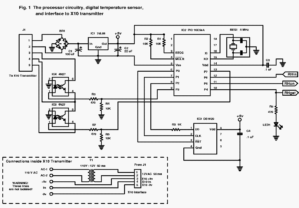
Pins 6, 7, and 8 are used to communicate to IC3, a Dallas DS1620 thermometer IC. This chip contains a built in temperature sensor and digital circuitry that outputs the data in 0.5 deg C. increments; this precision is approx. 1 deg. F. Typical error for a normal environment (about 0 to 120 deg. F) is well within the 1 deg. F resolution. C4 is an additional filter capacitor to reduce spurious high-frequency noise. Data is transmitted to/from input/output pin 1 of IC3, while pins 2 and 3 are inputs from IC2. More details on the DS1620 can be obtained from Dallas Semiconductor Corp.
Pins 10, 11, and 12 of IC2 are used to communicate to the humidity circuitry (more on this later). Pin 10 does double-duty by also driving LED1 through current limiting resistor R8. LED1 is used for monitoring and debugging, and as a human interface, but is not needed for operation otherwise.
Pins 9 and 13 are used as outputs to the X10 interface. A high (+5-volt) signal on pin 9 is used to send an 'on' signal to the X10 transmitter. A high signal on pin 13 sends an 'off' signal to the transmitter. The lines are kept low when not really sending signals by resistors R4 and R6. Resistors R5 and R7 limit the current to the light-emitting diodes in optoisolators IC4 and IC5. The outputs of these two ICs are NPN transistors that either conduct (send 'on' or 'off' signals to the X10 transmitter), when the LEDs are conducting, or are open circuits when no current passes through the diodes. The X10 interfacing is explained in more detail in the second part of this article.
Refer to Figure 2 to understand how the humidity circuit works. It is built around a relative humidity sensor, RH1, an NH-03 from Figaro USA Inc. It contains 2 humidity-sensitive elements made from a stable high polymer impregnated in porous ceramic, and 2 printed NTC thermistors. The elements are manufactured so that when an AC voltage of about 1-volt AC, approx. 1000 Hz is applied to the input (across pins 1 and 3), an output AC voltage is presented (across pins 1 and 2) so that this output AC voltage is proportional to % relative humidity. The linear, temperature-compensated output greatly reduces the problems that would be present for exponential-type outputs normally found with these types of sensors. However, there are two problems that present themselves: that of the AC input/output and the calibration of the AC signals.
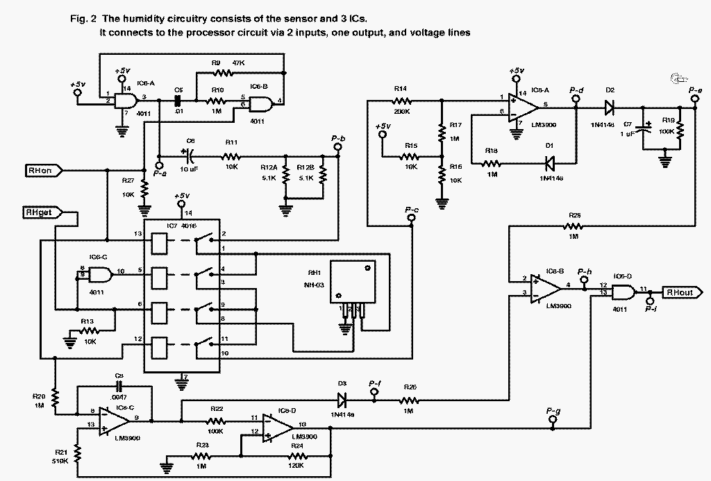
AC voltage is required for input to the humidity sensor. Any DC applied to the sensor will cause permanent damage to the sensor element and render it useless. Therefore, a simple DC resistance circuit is out of the question. However, AC circuits are relatively difficult to regulate. A 10% deviation in the input signal would translate to an error of 10% or more. A self-calibration technique is used to get around these problems.
Two sections of a CMOS NAND gate (IC6-A and IC6-B) are used to create a 5-volt square-wave generator. Pin 6 is used to gate the oscillator; when it is high (+5-volt), the circuit oscillates, while when it is low (0-volt), there is no oscillation. This gate is controlled by the CPU pin 11 (signal labeled 'RHon'. The R9-C5 combination sets the rate of oscillation. For the part values shown, it is approximately 1 kHz. Therefore, the output at pin 3 ('P-a' on Fig 2, pt 'a' on the PC board) is a 5-volt 1kHz gated square wave. C6 is used to translate this from a [+5v to 0v] signal to a [+2.5v to -2.5v] (true AC) signal. It is reduced to a 1-volt signal [+0.5v to -0.5v] by the divider made up of resistors R11 and R12. This 1-v 1-kHz AC signal can then be applied to the humidity sensor.
IC7 (a CMOS quad bilateral switch) and gate IC6-C (used as an inverter) form a switch that isolates the humidity sensor when the circuit is not really using measuring humidity. They also are used to switch either the input or the output to the measuring circuitry that follows it. When 'RHon' is high (+5v), the 1-v 1-kHz AC signal is applied to the input to the sensor, and an output is sent to the rest of the circuit. However, signal 'RHget' (from the CPU pin 10) is used to create a SPDT switch so that the output via pin 10 of IC7 is either the input to the sensor (when 'RHget' is high, the AC signal is passed from pin 2 to pin 1 to pin 4 to pin 3 to pin 11 and then to pin 10), to measure the 'control' signal, or the output of the sensor (when 'RHget' is low, the AC signal is passed through pin 2 through the sensor from its pin 3 to pin 2, to IC7 pin 8 to pin 9 to pin 11 and then to pin 10), to measure the 'test' signal.
The result of all of the above: when 'RHon' is high and 'RHget' is low, the output 'P-c' is the control signal (the input to the sensor), which at that point is the 1-v AC signal attenuated slightly by passing through 3 sections of IC7. When 'RHon' is high and 'RHget' is also high, the output 'P-c' is the test signal (the output from the sensor), which is an AC signal, typically less than 1-v AC and directly proportional to % RH; this signal is also attenuated slightly by passing through 3 sections of IC7. The CPU then measures two signals: the control signal and the test signal. Software inside the CPU's program divides the result from the test by the result from the control. This effectively cancels out any effects of voltage loss through IC7, deviations from 1 kHz, deviations from 1-v AC, deviations in the triangle waves or amps (see below), etc. It completely eliminates the need for any calibration whatsoever.
The rest of the circuit is used to create a signal that the CPU can measure that is in some way directly proportional to the level of AC voltage at 'P-c'. In this case it is a pulse width which the CPU measures. The signal at 'P-c' is an AC 1-kHz square wave that varies from approx. 1-v (for 'control' or for 100% RH 'test') to nearly 0-v (for about 30% RH 'test'). The amplifier IC8-A and resistors R14, 15, 16, 17, and D1 rectify the AC signal and amplify it to more measurable levels. D2, C7, and R19 filter it so that the signal at 'P-e' is a DC signal that is approx. 2.5v maximum, about 0.5v minimum.
IC8-C and IC8-D and associated components (R20, 21, 22, 23, and 24, and C8) form a precision triangle-wave generator, with a frequency of about 125 Hz. It also is gated (turned on) by a high level of 'RHon'. The output of the triangle wave is dropped a fraction of a volt through D3, so that the high tip of the triangle is at about 2.9v, while the low tip is about 0.4v, at 'P-f'. A square wave at the same frequency of the triangle is output via pin 10 of IC8-D ('P-g'); the square wave is high whenever the triangle is increasing (going from 0.4v to 2.9v), while it is low when the triangle is decreasing (going from 2.9v to 0.4v).
Another square wave is created by IC8-B, used as a comparator. Here this square wave at 'P-h' is high whenever the voltage of the triangle wave is less than the DC level at 'P-e'. The two square waves are gated by IC6-D NAND gate to form a pulse, that is at 0v only when the triangle wave is increasing and is at a lower voltage than the DC voltage at 'P-e'. The width of this negative pulse is therefore directly proportional to the DC voltage at 'P-e' and thus also proportional to the AC voltage at 'P-c'.
The humidity circuitry appears quite complex, as is its explanation. However, it uses 3 extremely inexpensive ICs and a handful of resistors, capacitors, and diodes. It is designed so that the results are virtually independent of any minor deviations in parts values, voltages, or frequencies. The results are almost totally defined by the precision and accuracy of the humidity sensor itself, and the cost of the circuitry of Fig. 2 is also almost totally defined by the cost of the sensor.
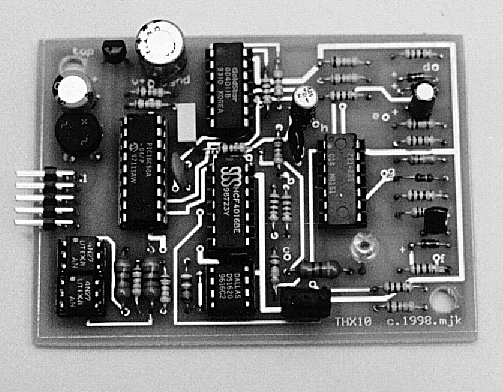
Except for the oscillator of the PIC CPU, no very high frequencies are involved, and voltages and currents are low. Therefore, any type of circuit construction (breadboarding, wire wrapping, etc.) will work fine. However, to keep the circuit small and to avoid wiring errors, a printed circuit is recommended. Foil patterns for the top and bottom of a double-sided board are included if you are adept at etching your own boards. For the rest of you, PC boards can be purchased from the author (see the parts list).
A preprogrammed PIC CPU containing the THX10 program can be purchased,
as well as the other hard-to-get parts (see the parts list). The humidity
sensor is available from the author and through Figaro; there is no substitute
for this item. Other transformers can be used to deliver 12 volts to the
circuit, but the part shown in the parts list is ideal for making a compact
system - it is only 0.6 inch tall, allowing a very thin case to be used.
You should have no trouble finding any of the other parts; sources for
some of them are shown in the parts list.
SEMICONDUCTORS
IC1 - 78L05 5-volt 100-ma voltage regulator
integrated circuit, TO-92 package
IC2 - PIC16C58A-04, Microchip 8-bit RISC
microcontroller integrated circuit programmed with THX10 program (see below)
IC3 - DS1620, Dallas digital thermometer
integrated circuit, Jameco #114382
IC4, IC5 - 4N27 (NTE/ECG #3040) optoisolator:
diode and NPN phototransistor integrated circuit, Jameco #144240 or Digi-Key
#4N27QT-ND
IC6 - CD4011 quad 2-input NAND gate CMOS
integrated circuit
IC7 - CD4016 quad bilateral switch CMOS
integrated circuit
IC8 - LM3900N or CA3401N quad current-mirror
op-amp integrated circuit
BR1 - W02G full wave bridge rectifier,
4 lead molded 200-PRV 1-Amp, Jameco #103018 or Digi-Key W02G-ND
D1, D2, D3 - 1N4148 or 1N914 silicon switching
diode 75-PRV 10-ma
LED1 - Light emitting diode, red
RESISTORS
(All resistors are 1/4 watt, 5% units
unless noted otherwise)
R1, R2, R4, R6, R11, R13, R15, R16, R27
- 10,000-ohm
R3 - 1000-ohm
R5, R7, R8 - 470-ohm
R9 - 47,000-ohm
R10, R17, R18, R20, R23, R25, R26 - 1.0-megohm
R12A, R12B - 5100-ohm (see text)
R14 - 200,000-ohm
R19, R22 - 100,000-ohm
R21 - 510,000-ohm
R24 - 120,000-ohm
CAPACITORS
C1 - 100-uF, 25-WVDC, electrolytic
C2 - 22-uF, 25-WVDC, electrolytic
C3, C4 - 0.1-uF, ceramic disk
C5 - 0.01-uF, 10% mylar
C6 - 10-uF, 25-WVDC, electrolytic
C7 - 1.0-uF, 25-WVDC, electrolytic
C8 - 0.0047-uF, 10% mylar
ADDITIONAL PARTS AND MATERIALS
J1 - 0.100" right angle male header 10
conductor (2X5), and matching IDC socket connector (such as Jameco S-10)
RES1 - 4.00-MHz ceramic resonator, Digi-Key
PX400-ND or equivalent
RH1 - NH-03 temperature-compensated linearized-AC
humidity sensor, available from Figaro USA, www.figarosensor.com (see below)
T1 - low profile transformer 115-V 60-Hz
primary, 12-V @ 50-ma secondary, SPK0051200-10001 or equivalent, available
from Advanced Components Industries, www.advancedcomponents.com (see below)
Mini-controller - X10 Powerhouse Transmitter
MC460 (Tech America #980-0213, Home Automation Systems-www.smarthome.com
#4030), or Home Controls Inc-www.homecontrols.com #XT460X) or similar products
by Stanley (Home Automation Systems #4031) or Radio Shack #61-2677c (see
text)
PC Interface - X10 Activehome CM11A (Home
Automation Systems-www.smarthome.com #1140), also available as part of
X10 home automation kit at Radio Shack stores, Home Controls Inc - www.homecontrols.com
#XTCK11A, etc. (see text)
IC sockets, PC board (see below), suitable enclosure, wire, hardware, PC and software, etc.
Note: the following items are available from M.Keryan, 207 Baucom Park Dr., Greer, SC 29650:
For R12, two 5100-ohm resistors are used in parallel to give a 2550-ohm equivalent. This is close enough to the desired 2500-ohm that would give an exact 1-volt p-p AC signal. If you can find one, use a single 2500-ohm 1% resistor installed in either the R12A or R12B position on the PC board. The only capacitors that are critical at all are C5 and C8. Make sure you use 10% mylar or better here to minimize timing drifts.
A red LED is specified in the parts list, but actually any color will do. You may want to splurge and get a high-brightness LED for about a dollar, instead of a standard brightness 20 cent LED. The brighter ones are easier to see from across the room.
There are no jumpers to worry about. Use IC sockets for all the ICs except the regulator, IC1. When soldering in IC1, the LED, and the diodes, take care to not overheat the leads; you may want to use a hemostat-type heat sink clamped to the leads. If you build your system like the author, you will want to stand the LED off the PCB so that it will fit into a hole drilled in the top side of the case. Using the placement diagram, solder in all the resistors and diodes (watch the diode orientation - the banded ends all point the same way, toward the left). Similarly, for the items that are partially round but have one flat side (IC1, BR1, LED1) - the flat ends all go toward the top of the board. RES1 can be oriented either way. RH1 must be oriented so that the front (the side with the two little 'M's) face the closest edge of the PC board.
After all the parts are soldered in, inspect your work to make sure
there are no solder bridges and that everything is clean and shiny (no
cold solder joints). Then plug in all the ICs, making sure all pin 1s (the
end with the dimple or notch) faces towards the top of the board. Take
the normal precautions to avoid static electricity discharges when handling
the ICs.
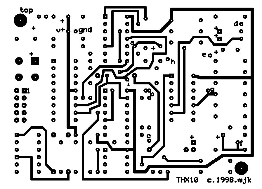
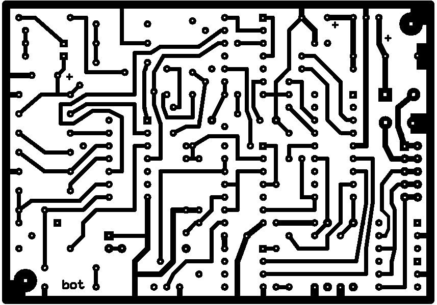
 (Click on the 3 images for full-size renditions)
To test the board after construction, connect either a 12-volt (AC or DC) supply or a 9-volt battery to pins 1 and 2 of J1, with no connections to pins 3, 4, and 5 of J1. After a few seconds, you should see the LED blink 3 times. This indicates that the CPU and program inside it are working. After about 10 more seconds, you should see the LED blink out the temperature, in degrees F. After about 5-6 minutes, you'll see the LED come on for about 2 seconds, then after about 10 more seconds, it will blink out the humidity, in %. Try breathing directly on the humidity sensor just before it takes a reading, and notice the change in humidity.
You may be wondering how a single LED can be used to blink out this information to you in a meaningful way. It blinks in one-second intervals -- 1/2 second on, 1/2 second off. One blink means 1, two blinks means 2, ... 9 blinks means 9. Between the hundreds and tens digits and between the tens and units digits, there is a longer gap, or pause. For a zero, there is a very short blink, one that is noticeably shorter than the others. For example consider a sequence like this: a very short blink - a pause - 7 blinks - a pause - 3 blinks; this is 0-7-3, or 73. The humidity is preceeded by about a 2 second long blink to differentiate it from temperature.
What about calibration? There isn't any. The Dallas thermometer chip (IC3) is truly digital; it sends binary data to the CPU. The humidity circuit (see section: 'The Humidity Circuit') uses a self-calibration technique. Any inaccuracies that occur are due to either the sensors themselves, or are due to their placement and the possibility that they might not be ventilated adequately.
The only thing that remains to be tested is the interface to the X10 transmitter. We'll do that when we describe how to connect the sensor board to the transmitter.
This concludes part one of the 2-part article. To this point, we have constructed a PC board that contains sensors for temperature and humidity, and a PIC CPU that processes the data and sends the data to an interface. In its current state, it is a self-contained instrument that can communicate its findings via a LED. Next time, we will explain how to interface this instrument to an inexpensive X10 mini-controller that transmits the data on our house power line. So, between now and then, build the sensor board and have fun watching the LED count. Later on, get the remaining parts: the mini-controller and the serial PC interface that will be used to receive the data on up to 8 of the transmitters. Also make sure you have a free serial port on your PC.
' Program T_H_X10.BAS written in PBASIC
for BASIC STAMP I
' For programmed PIC16C58A-04, email mkeryan@pobox.com
' Copyright 1998 Mike Keryan
' Interfaces: input
Dallas DS1620 Digital Temperature IC
'
input Figaro NH-03 Humidity sensor and associated
'
circuitry giving a variable width pulse
'
output single Led, used to display data
'
output two relays, one for on-bit, one for off-bit
'
these control an X-10 control interface
'
' The system grabs either temperature
(from a digital temperature IC)
' or humidity (from a linear humidity-dependent
resistive sensor)
' alternately every 5 minutes. Each one
is updated every 10 minutes.
' The display is a single Led which blinks
the appropriate number
' of times to count out each digit of
the temperature or humid. data.
' Captured data is output to the X-10
controller as a series of 8
' on or off bits. Temperature data is
in deg. F., Humidity sent via
' X-10 is % relative humidity, with the
last bit set (+128), so that
' receiving program monitoring X-10 line
can tell which is which.
'----------input/output pins
SYMBOL RST = 0
' PIN0 is reset for DS1620
SYMBOL CLK = 1
' PIN1 is clock for DS1620
SYMBOL DQn = 2
' PIN2 is data i/o for DS1620
SYMBOL DQp = pin2 ' PIN2 for
inputting, outputting a bit
SYMBOL RelayOn = 3 ' PIN3 is relay
output for on state
SYMBOL Led = 4
' PIN4 is output to Led
SYMBOL RHget = 4 ' PIN4
also used to switch between:
'
0 = applied voltage measured
'
1 = response voltage measured
SYMBOL RHon = 5
' PIN5 high activates RH circuitry
SYMBOL RHin = 6
' PIN6 is input pulse for RH
SYMBOL RelayOff = 7 ' PIN7 is relay output
for off state
'----------variable storage
SYMBOL DSout = W0
' data to DS1620; W0 overlaps B0, B1,
SYMBOL DSin = W0
' data from DS1620; and BIT0-BIT7,
SYMBOL DSDat = W0
' data in DS format; and BIT8-BIT15
SYMBOL BitOut = BIT0 ' output data
one bit at a time
SYMBOL BitIn = BIT8 ' input
data one bit at a time
SYMBOL SignBit = BIT8 ' data is negative
(deg C) when this bit is set
SYMBOL CountSec = B4 ' 8 bit counter
for 2.3 second increments
SYMBOL WhichOne = B5 ' 1 = temperature,
0 = humidity
SYMBOL HumiData = B6 ' humidity,
% RH
SYMBOL TempData = B6 ' temperature,
deg F
SYMBOL LedData = B6 ' data
to pulse out on LED
SYMBOL Unused = B7 '
SYMBOL DataOut = B8 ' data
to send to relays
SYMBOL Pulses = B9 '
8 bit register for counting pulses
SYMBOL I = B10
' index for loop
SYMBOL J = B11
' temporary variable
SYMBOL ABit = B11
' bit sent to relays
SYMBOL V0 = W1
' pulse width for applied voltage to hum. sensor
' W1 overlaps B2 and B3
SYMBOL V1 = W6
' pulse width for response voltage from hum. sensor
' W6 overlaps B12, B13 which are used during GOSUBS
'----------constants
SYMBOL WConfig = $0C ' code to write
to configuration register
SYMBOL CPU = %10
' configuration bit for thermometer mode
SYMBOL OneShot = %01 ' configuration
bit for one conversion only
SYMBOL StartC = $EE ' code
to start conversion
SYMBOL RTemp = $AA '
code to read temperature out of DS1620
'----------initialize the DS1620 chip's
EEPROM at power-up
LOW RST
' deactivate DS1620
HIGH CLK
' initially high per specs
PAUSE 2000
' let everything stabilize
DSout = WConfig
' write configuration
GOSUB ShiftOut
' to DS1620
DSout = CPU + OneShot ' thermometer
in 1-shot mode
GOSUB ShiftOut
' to DS1620
LOW RST
' deactivate DS1620
Pulses = 3
' send 3 long blinks
GOSUB BlinkLed
' to tell its on and working
'----------continually loop between here
and end
Loop:
WhichOne = WhichOne + 1 & 1
' counts 1, 0, 1, 0, 1, ...
IF WhichOne = 1 THEN Temper
'----------get humidity data when WhichOne
= 0
Humid:
HIGH RHon
' turn on humidity circuitry
PAUSE 2000
' wait till stable
PULSIN RHin, 0, V0
' get pulse width for V0 (applied)
IF V0 < 10 THEN Humid '
eliminate glitches
HIGH RHget
' switch from applied to response
PAUSE 1000
' wait till stable
PULSIN RHin, 0, V1
' get pulse width for V1 (response)
LOW RHget
' shut down V1 output
LOW RHon
' shut down humidity circuit
HumiData = 140 * V1 / V0 + 61 /
2 ' % relative humidity
DataOut = HumiData + 128
' set high bit
GOTO Relays
'----------get temperature data when WhichOne
= 1
Temper:
DSout = StartC
' code to start a temp. conversion
GOSUB ShiftOut
' to DS1620
LOW RST
' deactivate DS1620
PAUSE 2000
' wait for conversion to end
' and additional second
DSout = RTemp
' code to get the temperature
GOSUB ShiftOut
' to DS1620
'----------read data from DS1620 chip
INPUT DQn
' make pin an input
FOR I = 1 TO 9
' for 9 bits
DSin = DSin / 2
' shift right 1 bit
LOW CLK
' falling clock triggers DS1620
BitIn = DQp
' get the data bit
HIGH CLK
' preset clock high
NEXT I
LOW RST
' deactivate DS1820
IF SignBit = 0 THEN Skip
' this means neg. deg. C
DSDat = DSDat | $FE00
' make 16-bit 2's compl.
Skip:
TempData = DSDat * 9 + 325 / 10
' convert to deg. F
DataOut = TempData
'----------send data to relays
Relays:
FOR I = 1 TO 8
' for 8 bits
ABit = DataOut & 1
' lowest bit
IF ABit = 1 THEN HiBit
LowBit: HIGH RelayOff
' pulse for off state relay
GOTO RelayDelay
HiBit:
HIGH RelayOn
' pulse for on state relay
RelayDelay:
PAUSE 500
' 0.5 second on time
LOW RelayOff
' turn off
LOW RelayOn
' both relays
PAUSE 1500
' 1.5 second off time
DataOut = DataOut / 2 ' shift
to next bit
NEXT I
'----------display temperature by blinking
led
Display:
Pulses = LedData / 100 ' hundreds
GOSUB BlinkLed
' blink that many hundreds
Pulses = Pulses * 100
' either 0, 100, or 200
J = LedData - Pulses
' tens and units
Pulses = J / 10
' tens only
GOSUB BlinkLed
' blink that many tens
Pulses = J // 10
' units only
GOSUB BlinkLed
' blink that many ones
'----------loop consumes 5 minutes, mostly
in low-power mode
Loop5min:
FOR CountSec = 1 TO 130 '
about 5 minutes per loop
SLEEP 1
' low power for 2.3 seconds
NEXT CountSec
GOTO Loop
' redo everything
END
'----------send data to DS1620 chip
ShiftOut:
HIGH RST
' activate DS1620
OUTPUT DQn
' make pin an output
FOR I = 1 TO 8
' for 8 bits
LOW CLK
' preset clock low
DQp = BitOut
' data bit to DS1620
HIGH CLK
' rising clock triggers DS1620
DSout = DSout / 2
' shift right for next bit
NEXT I
RETURN
'----------blink the led a certain number
of times
BlinkLed:
HIGH Led
' turn on Led
PAUSE 10
' at least a short blink
IF Pulses = 0 THEN DoneBlink
' for zero count, skip loop
FOR I = 1 to Pulses
' do how many times
HIGH Led
' turn on Led
PAUSE 500
' wait 0.5 second
LOW Led
' turn off Led
PAUSE 500
' wait 0.5 second
NEXT I
DoneBlink:
LOW Led
' turn off Led
PAUSE 1000
' wait a second
RETURN